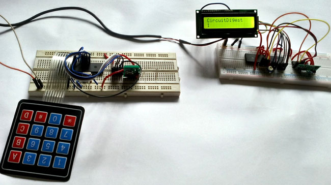
PIC to PIC Communication using RF Module
Components Required:
- 2 - Bread board
- 1 - LCD 16x2
- 1 – Keypad
- HT12D and HT12E pair
- RX-TX RF Module
- 1- 10K preset
- 2 – 4.7k resistor
- 1- 1M Resistor
- 1- 33k resistor
- 2- 33pF ceramic capacitors
- 1 – 20Mhz crystal
- Bergsticks
- Few single strand wires.
- PIC16F877A MCU
- PIC18F4520 MCU
- A screw driver for controlling the frequency pot, need to be insulated from human body.
Project Code
/*
* File: main.c
* Author: Sourav Gupta
* By:- circuitdigest.com
* Created on April 13, 2018, 2:26 PM
*/
* File: main.c
* Author: Sourav Gupta
* By:- circuitdigest.com
* Created on April 13, 2018, 2:26 PM
*/
// PIC16F877A Configuration Bit Settings
// 'C' source line config statements
// CONFIG
#pragma config FOSC = HS // Oscillator Selection bits (HS oscillator)
#pragma config WDTE = OFF // Watchdog Timer Enable bit (WDT disabled)
#pragma config PWRTE = OFF // Power-up Timer Enable bit (PWRT disabled)
#pragma config BOREN = ON // Brown-out Reset Enable bit (BOR enabled)
#pragma config LVP = OFF // Low-Voltage (Single-Supply) In-Circuit Serial Programming Enable bit (RB3/PGM pin has PGM function; low-voltage programming enabled)
#pragma config CPD = OFF // Data EEPROM Memory Code Protection bit (Data EEPROM code protection off)
#pragma config WRT = OFF // Flash Program Memory Write Enable bits (Write protection off; all program memory may be written to by EECON control)
#pragma config CP = OFF // Flash Program Memory Code Protection bit (Code protection off)
#include <xc.h>
#include <stdio.h>
#include <string.h>
#include "supporing_cfile/Keypad.h"
#define RF_TX PORTD
#include <stdio.h>
#include <string.h>
#include "supporing_cfile/Keypad.h"
#define RF_TX PORTD
/*
Hardware related definition
*/
#define _XTAL_FREQ 200000000 //Crystal Frequency, used in delay
Hardware related definition
*/
#define _XTAL_FREQ 200000000 //Crystal Frequency, used in delay
/*
Other Specific definition
*/
void system_init(void);
void encode_rf_sender (char data);
Other Specific definition
*/
void system_init(void);
void encode_rf_sender (char data);
void main(void){
system_init();
char Key = 'n';
while(1){
Key = switch_press_scan();
encode_rf_sender(Key);
}
system_init();
char Key = 'n';
while(1){
Key = switch_press_scan();
encode_rf_sender(Key);
}
}
/*
* System Init
*/
* System Init
*/
void system_init(void){
TRISD = 0x00;
RF_TX = 0x00;
keyboard_initialization();
}
void encode_rf_sender (char data){
if(data=='1')
RF_TX=0x10;
if(data=='2')
RF_TX=0x20;
if(data=='3')
RF_TX=0x30;
if(data=='4')
RF_TX=0x40;
if(data=='5')
RF_TX=0x50;
if(data=='6')
RF_TX=0x60;
if(data=='7')
RF_TX=0x70;
if(data=='8')
RF_TX=0x80;
if(data=='9')
RF_TX=0x90;
if(data=='0')
RF_TX=0x00;
if(data=='*')
RF_TX=0xa0;
if(data=='#')
RF_TX=0xb0;
if(data=='A')
RF_TX=0xc0;
if(data=='B')
RF_TX=0xd0;
if(data=='C')
RF_TX=0xe0;
if(data=='D')
RF_TX=0xf0;
}
PIC code for Receiver Side:
/*
* File: main.c
* Author: Sourav Gupta
*CircuitDigest.com
* Created on 17 May 2018, 12:18
*/
* File: main.c
* Author: Sourav Gupta
*CircuitDigest.com
* Created on 17 May 2018, 12:18
*/
// PIC18F4520 Configuration Bit Settings
// 'C' source line config statements
// CONFIG1H
#pragma config OSC = INTIO7 // Oscillator Selection bits (Internal oscillator block, CLKO function on RA6, port function on RA7)
#pragma config FCMEN = OFF // Fail-Safe Clock Monitor Enable bit (Fail-Safe Clock Monitor disabled)
#pragma config IESO = OFF // Internal/External Oscillator Switchover bit (Oscillator Switchover mode disabled)
// CONFIG2L
#pragma config PWRT = OFF // Power-up Timer Enable bit (PWRT disabled)
#pragma config BOREN = SBORDIS // Brown-out Reset Enable bits (Brown-out Reset enabled in hardware only (SBOREN is disabled))
#pragma config BORV = 3 // Brown Out Reset Voltage bits (Minimum setting)
#pragma config PWRT = OFF // Power-up Timer Enable bit (PWRT disabled)
#pragma config BOREN = SBORDIS // Brown-out Reset Enable bits (Brown-out Reset enabled in hardware only (SBOREN is disabled))
#pragma config BORV = 3 // Brown Out Reset Voltage bits (Minimum setting)
// CONFIG2H
#pragma config WDT = ON // Watchdog Timer Enable bit (WDT enabled)
#pragma config WDTPS = 32768 // Watchdog Timer Postscale Select bits (1:32768)
#pragma config WDT = ON // Watchdog Timer Enable bit (WDT enabled)
#pragma config WDTPS = 32768 // Watchdog Timer Postscale Select bits (1:32768)
// CONFIG3H
#pragma config CCP2MX = PORTC // CCP2 MUX bit (CCP2 input/output is multiplexed with RC1)
#pragma config PBADEN = OFF // PORTB A/D Enable bit (PORTB<4:0> pins are configured as analog input channels on Reset)
#pragma config LPT1OSC = OFF // Low-Power Timer1 Oscillator Enable bit (Timer1 configured for higher power operation)
#pragma config MCLRE = ON // MCLR Pin Enable bit (MCLR pin enabled; RE3 input pin disabled)
// CONFIG4L
#pragma config STVREN = ON // Stack Full/Underflow Reset Enable bit (Stack full/underflow will cause Reset)
#pragma config LVP = OFF // Single-Supply ICSP Enable bit (Single-Supply ICSP disabled)
#pragma config XINST = OFF // Extended Instruction Set Enable bit (Instruction set extension and Indexed Addressing mode disabled (Legacy mode))
// CONFIG5L
#pragma config CP0 = OFF // Code Protection bit (Block 0 (000800-001FFFh) not code-protected)
#pragma config CP1 = OFF // Code Protection bit (Block 1 (002000-003FFFh) not code-protected)
#pragma config CP2 = OFF // Code Protection bit (Block 2 (004000-005FFFh) not code-protected)
#pragma config CP3 = OFF // Code Protection bit (Block 3 (006000-007FFFh) not code-protected)
// CONFIG5H
#pragma config CPB = OFF // Boot Block Code Protection bit (Boot block (000000-0007FFh) not code-protected)
#pragma config CPD = OFF // Data EEPROM Code Protection bit (Data EEPROM not code-protected)
#pragma config CPB = OFF // Boot Block Code Protection bit (Boot block (000000-0007FFh) not code-protected)
#pragma config CPD = OFF // Data EEPROM Code Protection bit (Data EEPROM not code-protected)
// CONFIG6L
#pragma config WRT0 = OFF // Write Protection bit (Block 0 (000800-001FFFh) not write-protected)
#pragma config WRT1 = OFF // Write Protection bit (Block 1 (002000-003FFFh) not write-protected)
#pragma config WRT2 = OFF // Write Protection bit (Block 2 (004000-005FFFh) not write-protected)
#pragma config WRT3 = OFF // Write Protection bit (Block 3 (006000-007FFFh) not write-protected)
// CONFIG6H
#pragma config WRTC = OFF // Configuration Register Write Protection bit (Configuration registers (300000-3000FFh) not write-protected)
#pragma config WRTB = OFF // Boot Block Write Protection bit (Boot block (000000-0007FFh) not write-protected)
#pragma config WRTD = OFF // Data EEPROM Write Protection bit (Data EEPROM not write-protected)
// CONFIG7L
#pragma config EBTR0 = OFF // Table Read Protection bit (Block 0 (000800-001FFFh) not protected from table reads executed in other blocks)
#pragma config EBTR1 = OFF // Table Read Protection bit (Block 1 (002000-003FFFh) not protected from table reads executed in other blocks)
#pragma config EBTR2 = OFF // Table Read Protection bit (Block 2 (004000-005FFFh) not protected from table reads executed in other blocks)
#pragma config EBTR3 = OFF // Table Read Protection bit (Block 3 (006000-007FFFh) not protected from table reads executed in other blocks)
// CONFIG7H
#pragma config EBTRB = OFF // Boot Block Table Read Protection bit (Boot block (000000-0007FFh) not protected from table reads executed in other blocks)
#pragma config EBTRB = OFF // Boot Block Table Read Protection bit (Boot block (000000-0007FFh) not protected from table reads executed in other blocks)
// #pragma config statements should precede project file includes.
// Use project enums instead of #define for ON and OFF.
// Use project enums instead of #define for ON and OFF.
#include <xc.h>
#include "supporing_cfile\lcd.h"
#include "supporing_cfile\lcd.h"
#define RF_RX PORTD
void system_init (void);
void rf_analysis (unsigned char recived_byte);
void rf_analysis (unsigned char recived_byte);
void main(void) {
unsigned char byte = 0;
system_init();
lcd_init();
while(1){
lcd_com(0x80);
lcd_puts("CircuitDigest");
lcd_com (0xC0);
byte = RF_RX;
rf_analysis(byte);
lcd_com (0xC0);
}
return;
}
unsigned char byte = 0;
system_init();
lcd_init();
while(1){
lcd_com(0x80);
lcd_puts("CircuitDigest");
lcd_com (0xC0);
byte = RF_RX;
rf_analysis(byte);
lcd_com (0xC0);
}
return;
}
void system_init (void){
OSCCON = 0b01111110; // 8Mhz, , intosc
//OSCTUNE = 0b01001111; // PLL enable, Max prescaler 8x4 = 32Mhz
TRISB = 0x00;
TRISD = 0xFF; // Last 4 bit as input bit.
}
OSCCON = 0b01111110; // 8Mhz, , intosc
//OSCTUNE = 0b01001111; // PLL enable, Max prescaler 8x4 = 32Mhz
TRISB = 0x00;
TRISD = 0xFF; // Last 4 bit as input bit.
}
void rf_analysis (unsigned char recived_byte){
if(recived_byte==0x10)
lcd_data('1');
if(recived_byte==0x20)
lcd_data('2');
if(recived_byte==0x30)
lcd_data('3');
if(recived_byte==0x40)
lcd_data('4');
if(recived_byte==0x50)
lcd_data('5');
if(recived_byte==0x60)
lcd_data('6');
if(recived_byte==0x70)
lcd_data('7');
if(recived_byte==0x80)
lcd_data('8');
if(recived_byte==0x90)
lcd_data('9');
if(recived_byte==0x00)
lcd_data('0');
if(recived_byte==0xa0)
lcd_data('*');
if(recived_byte==0xb0)
lcd_data('#');
if(recived_byte==0xc0)
lcd_data('A');
if(recived_byte==0xd0)
lcd_data('B');
if(recived_byte==0xe0)
lcd_data('C');
if(recived_byte==0xf0)
lcd_data('D');
}


ไม่มีความคิดเห็น:
แสดงความคิดเห็น