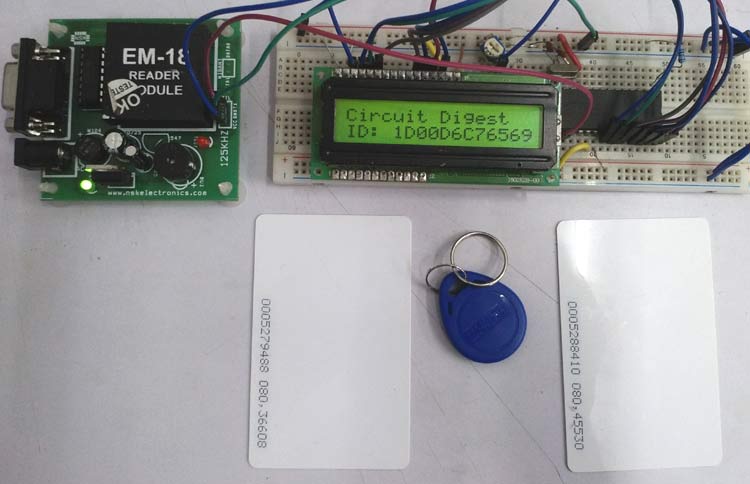
RFID Interfacing with PIC Microcontroller

Material Required
To make this project we need following items-
- PIC16F877A
- 20Mhz Crystal
- 2pcs 33pF ceramic disc capacitor
- 16x2 Character LCD
- A breadboard
- 10k preset pot
- 4.7k resistor
- Single strand wires to connect
- A 5V adapter
- RF Module EM-18
- 5V Buzzer
- 100uF & .1uF 12V capacitor
- BC557 Transistor
- LED
- 2.2k and 470R resistor.
Project Code
/*
* File: main.c
* Author: Sourav Gupta
* By:- circuitdigest.com
* Created on August 15, 2018, 2:26 PM
*/
* File: main.c
* Author: Sourav Gupta
* By:- circuitdigest.com
* Created on August 15, 2018, 2:26 PM
*/
// PIC16F877A Configuration Bit Settings
// 'C' source line config statements
// CONFIG
#pragma config FOSC = HS // Oscillator Selection bits (HS oscillator)
#pragma config WDTE = OFF // Watchdog Timer Enable bit (WDT disabled)
#pragma config PWRTE = OFF // Power-up Timer Enable bit (PWRT disabled)
#pragma config BOREN = ON // Brown-out Reset Enable bit (BOR enabled)
#pragma config LVP = OFF // Low-Voltage (Single-Supply) In-Circuit Serial Programming Enable bit (RB3/PGM pin has PGM function; low-voltage programming enabled)
#pragma config CPD = OFF // Data EEPROM Memory Code Protection bit (Data EEPROM code protection off)
#pragma config WRT = OFF // Flash Program Memory Write Enable bits (Write protection off; all program memory may be written to by EECON control)
#pragma config CP = OFF // Flash Program Memory Code Protection bit (Code protection off)
#include <xc.h>
#include <stdio.h>
#include <string.h>
#include "supporing_cfile\lcd.h"
#include "supporing_cfile\eusart1.h"
#include <stdio.h>
#include <string.h>
#include "supporing_cfile\lcd.h"
#include "supporing_cfile\eusart1.h"
/*
Hardware related definition
*/
#define _XTAL_FREQ 200000000 //Crystal Frequency, used in delay
Hardware related definition
*/
#define _XTAL_FREQ 200000000 //Crystal Frequency, used in delay
/*
Other Specific definition
*/
void system_init(void); // This will initialize the system.
Other Specific definition
*/
void system_init(void); // This will initialize the system.
void main(void) {
unsigned char count;
unsigned char RF_ID[13];
system_init();
lcd_com(0x80);
lcd_puts("Circuit Digest");
while (1){
for (count=0; count<12; count++){
RF_ID[count] = 0;
RF_ID[count]=EUSART1_Read();
}
lcd_com(0xC0); // Set the cursor for second line begining
lcd_puts("ID: ");
lcd_puts(RF_ID);
}
}
unsigned char count;
unsigned char RF_ID[13];
system_init();
lcd_com(0x80);
lcd_puts("Circuit Digest");
while (1){
for (count=0; count<12; count++){
RF_ID[count] = 0;
RF_ID[count]=EUSART1_Read();
}
lcd_com(0xC0); // Set the cursor for second line begining
lcd_puts("ID: ");
lcd_puts(RF_ID);
}
}
/*
This Function is for system initializations.
*/
This Function is for system initializations.
*/
void system_init(void){
TRISB = 0x00; //PORT B set as output pin
lcd_init(); // This will initialize the lcd
EUSART1_Initialize(); // This will initialize the Eusart
}
TRISB = 0x00; //PORT B set as output pin
lcd_init(); // This will initialize the lcd
EUSART1_Initialize(); // This will initialize the Eusart
}


ไม่มีความคิดเห็น:
แสดงความคิดเห็น