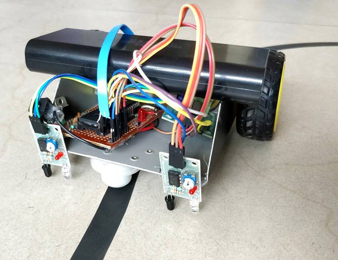
Line Follower Robot using PIC Microcontroller

Materials Required:
- PIC16F877A
- IR Sensor (2Nos)
- DC Gear Motor (2Nos)
- L293D Motor Driver
- Chaises (You can also build your own using cardboards)
- Power bank (Any available power source)
Project Code
/*
Line Follower using PIC16F877A
* Code by: B.Aswinth Raj
* Dated: 11-09-2017
* More details at: www.CircuitDigest.com
*/
Line Follower using PIC16F877A
* Code by: B.Aswinth Raj
* Dated: 11-09-2017
* More details at: www.CircuitDigest.com
*/
#include <xc.h>
#pragma config FOSC = HS // Oscillator Selection bits (HS oscillator)
#pragma config WDTE = OFF // Watchdog Timer Enable bit (WDT disabled)
#pragma config PWRTE = ON // Power-up Timer Enable bit (PWRT enabled)
#pragma config BOREN = ON // Brown-out Reset Enable bit (BOR enabled)
#pragma config LVP = OFF // Low-Voltage (Single-Supply) In-Circuit Serial Programming Enable bit (RB3 is digital I/O, HV on MCLR must be used for programming)
#pragma config CPD = OFF // Data EEPROM Memory Code Protection bit (Data EEPROM code protection off)
#pragma config WRT = OFF // Flash Program Memory Write Enable bits (Write protection off; all program memory may be written to by EECON control)
#pragma config CP = OFF // Flash Program Memory Code Protection bit (Code protection off)
void main()
{
TRISD2 = 1; TRISD3 = 1; //Bath the IR sensor pins are declared as input
TRISC4 = 0; TRISC5 = 0; //Motor 1 pins declared as output
TRISC6 = 0; TRISC7 = 0; //Motor 2 pins declared as output
while(1)
{
if (RD2==1 && RD3==1) //Both sensor not over balck line
{
RC4=0; RC5=1; //Motor 1 forward
RC6=1; RC7=0; //Motor 2 forward
}
else if (RD2==0 && RD3==1) //Left sensor is over black line
{
RC4=1; RC5=1; //Motor 1 stop
RC6=1; RC7=0; //Motor 2 forward
}
else if (RD2==1 && RD3==0) //Right sensor is over black line
{
RC4=0; RC5=1; //Motor 1 forward
RC6=1; RC7=1; //Motor 2 stop
}
else //Both Sensor over black line
{
RC4=1; RC5=1; //Motor 1 stop
RC6=1; RC7=1; //Motor 2 stop
}
}
}
{
TRISD2 = 1; TRISD3 = 1; //Bath the IR sensor pins are declared as input
TRISC4 = 0; TRISC5 = 0; //Motor 1 pins declared as output
TRISC6 = 0; TRISC7 = 0; //Motor 2 pins declared as output
while(1)
{
if (RD2==1 && RD3==1) //Both sensor not over balck line
{
RC4=0; RC5=1; //Motor 1 forward
RC6=1; RC7=0; //Motor 2 forward
}
else if (RD2==0 && RD3==1) //Left sensor is over black line
{
RC4=1; RC5=1; //Motor 1 stop
RC6=1; RC7=0; //Motor 2 forward
}
else if (RD2==1 && RD3==0) //Right sensor is over black line
{
RC4=0; RC5=1; //Motor 1 forward
RC6=1; RC7=1; //Motor 2 stop
}
else //Both Sensor over black line
{
RC4=1; RC5=1; //Motor 1 stop
RC6=1; RC7=1; //Motor 2 stop
}
}
}


ไม่มีความคิดเห็น:
แสดงความคิดเห็น